How to Draw on the Same Plane in Rhino
COMPUTER AIDED ARCHITECTURAL Design
Workshop 4 Notes, Week of September 23, 2012
INTRO TO SURFACES IN RHINO, CONTRUCTION PLANES IN Rhino REVISITED
i. SURFACES
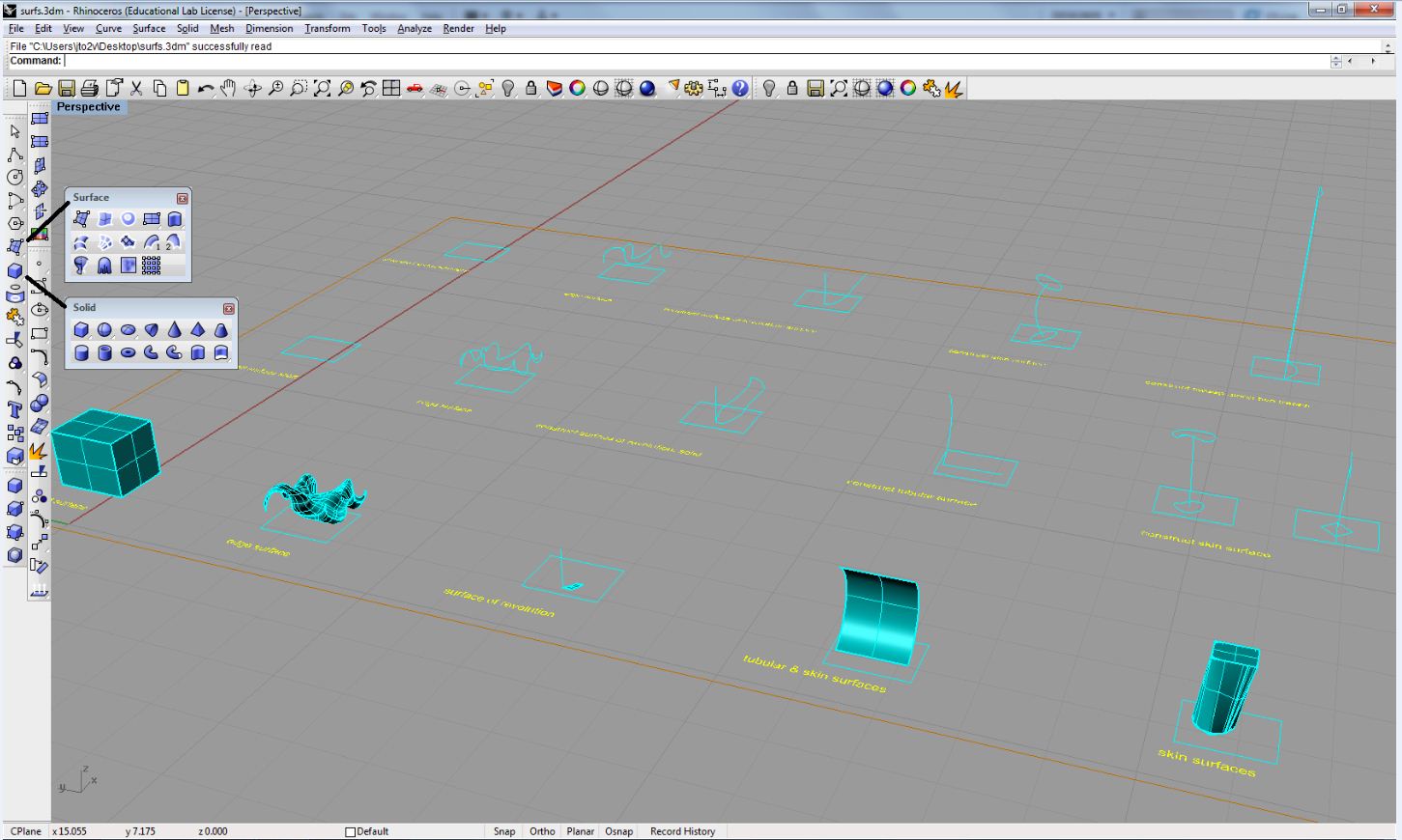
Load the file Classes\Arch3410-6410-Marking-F11\Examples\surfaces\surfs.3dm. In the Principal tool box, click and hold the surface icon to open up up the Surface modeling tool box and then click and concord the solids icon to open up the Solid modeling tool box, and use the tool specified in each case of a surface type entity as indicated below.
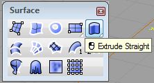
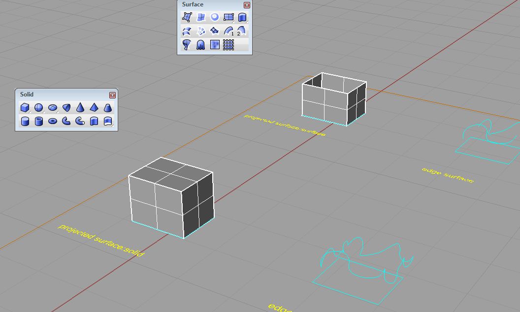
- Surface and Solid of Extrustion
Select Extrude Straight from the Surface toolbox (top correct icon below).
Select the rectangle in the upper left mitt corner, then press enter to interactively extrude it along the Z centrality.
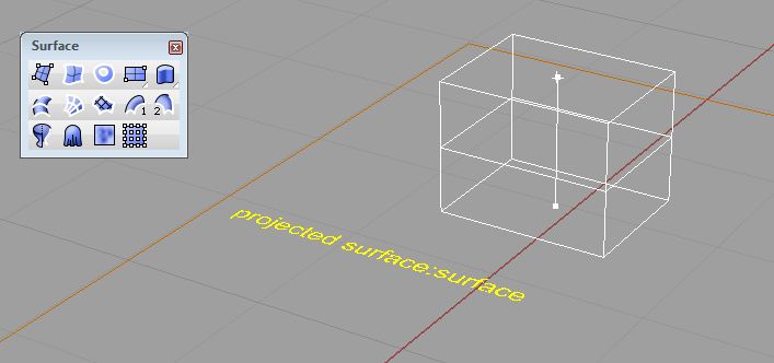
Select Extrude closed planar bend from the Solid tool box (bottom right icon below)
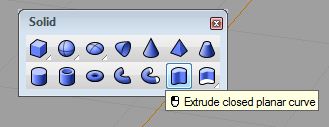
Select the rectangle in the upper left hand corner, and then press enter to ineractively extrude information technology along the Z axis.
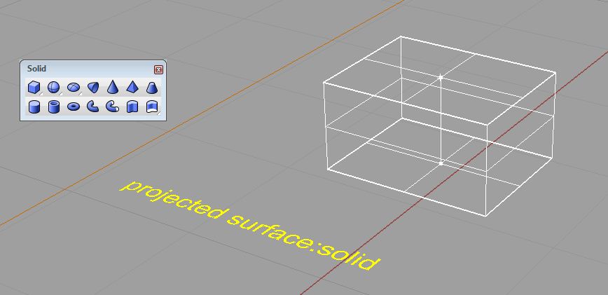
Notation the solid by extrusion is filled in, wheras the surface by extrusion is an open container.
- Select the Surface from 2, 3 or four Edge Curves icon from the Surface tool box.
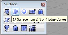
Printing enter and then select in clockwise or counter-clockwise guild the 4 edges assocaited with the figure below, once the fourth border is selected the surface volition automatically be generated.
The same tool applies to 2 parallel edges. Two initial cuved bspline established the edges used to generate the figure beneath. Each one of the initial bspline edges was selected to the aforementioned side of their respective mid-points, then enter was pressed to generate the surface below.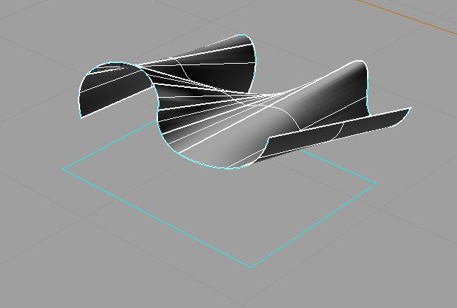
- Surface and Solid of Revolution.
The Revolve Surface icon is selected from the Surface tool box as shown below. The contour bend is selected by clicking on the curve and pressing enter, followed by end snaps onto the vertical axis line and finally pressing enter to set the start angle. The curve tin can then exist interactively swept about the axis or swept a total 360 degrees past pressing enter a final time.
The same technique also applies to a an open up contour bend.
- Tubular Surface
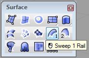
A tubular surface is obtained by the use of the Sweep 1 rails tool.
The first option for this tool is used in the case of simple line along the ground and a 3D profile curve. Select the contour curve, the horizontal line along the basis, and and then enter to bring up the Sweep runway 1 options dialog box.
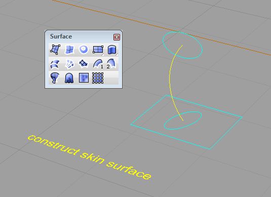
- Peel Surface
The aforementioned tool from earlier can be used to sweep two curves forth ane profile bend.
The cases beneath involve the use of similar techniques of sweeping 2 curves along a profile curve.

The Sweep 1 rail icon is selected followed by the path curve select the two contour curves 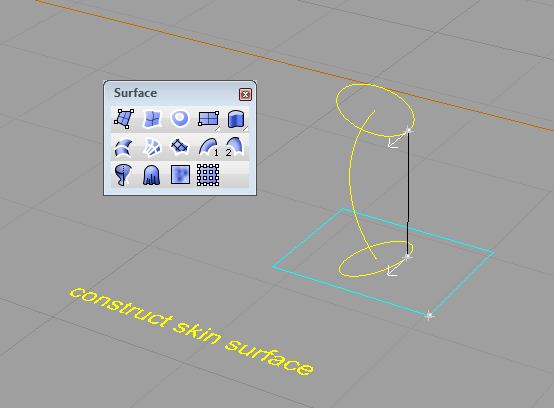
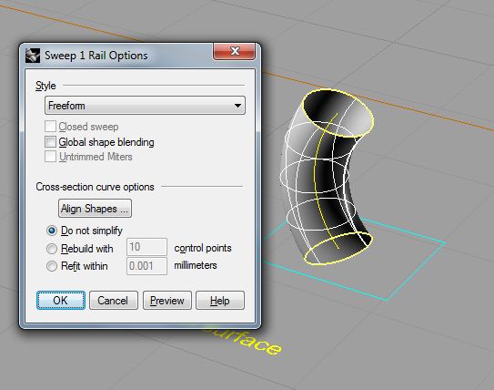
enter brings up the tool for adjusting the curve directions, make certain both arrows face the aforementioned direction. enter again brings up the options dialog, press ok to complete the surface. 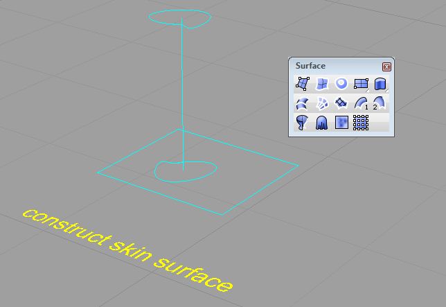
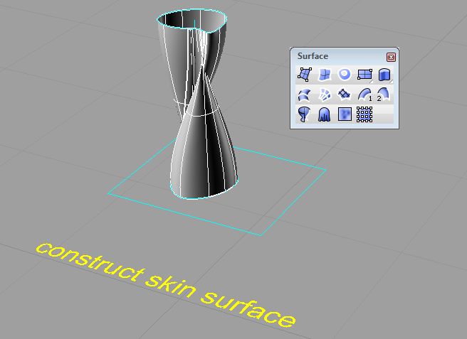
The Sweep i rail is selected for the case to a higher place. Select the two profile curves and enter to bring upwards the options dialog, enter again to complete the surface.
A variation on this blazon surface involves sweeping two curves forth two curves.
- The above operations produce the following result:
2. Coordinate Systems in Rhinoceros
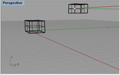
When cartoon in Rhino, objects are snapped into a 2d invisible airplane called a Construction Plane or CPlane. In perspective view if you are near the origin of the model space and grid is turned on (default) y'all can see the CPlane every bit the grid with the X and Y coordinates represented as red and green lines on this grid respectively. In the bottom left of this image is too an icon that shows the Global Coordinate Arrangement relative to the view window.
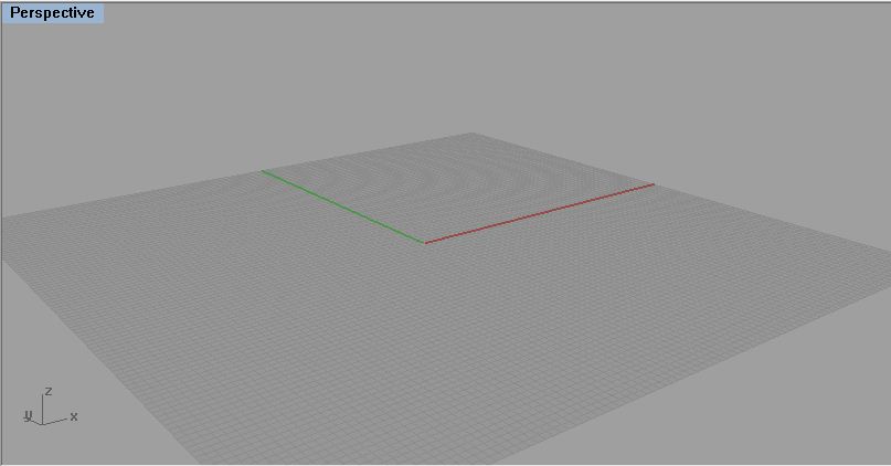
CPlane = Construction Plane, the invisible second plane which information points are snapped to. Changes relative to the different views.
Global Coordinate Arrangement = Represents the XYZ orientation of the model. Does non change relative to the unlike views or CPlanes. Past default, it is co-planar with the CPlanes.
5. Manipulating CPlanes and coordinate systems.
ane. CPlanes in Rhino tin be moved or rotated to whatever orientation to allow for better control of drawing in the model space
Setting CPlanes in Rhinoceros
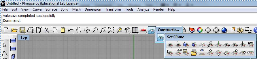
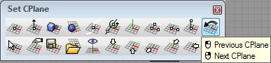
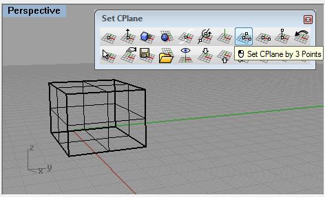
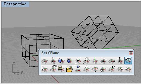
- Click and hold on the icon in the Chief button bar called Set up CPlane : origin to open up up the Coordinate System bar as its own window. So Click and concord the first icon in that bar to open up up the Set CPlane bar as another independent window.
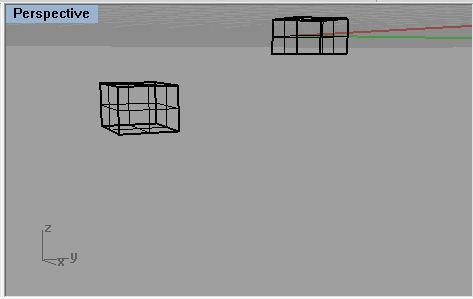
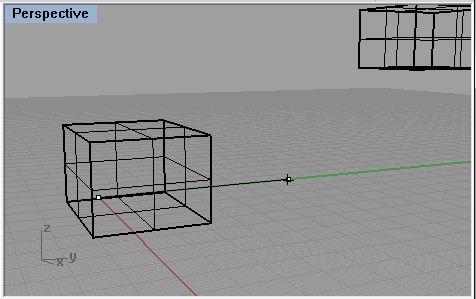
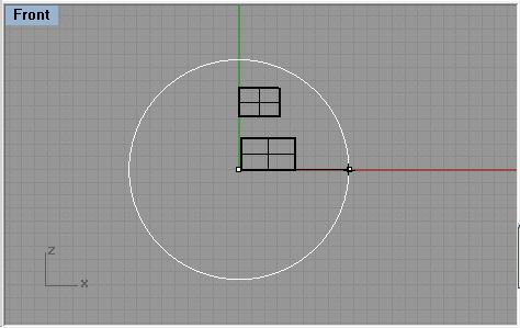
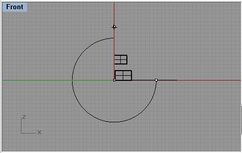
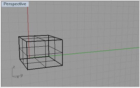
In perspective view draw a simple box, observe how the data points defining its length and width default to the Filigree of the CPlane. Now draw another box starting in the side view away from the origin, notice its position once extuded in the Perspective view off of the Perspective CPlane.
1.1 Translating the CPlane
Click on the outset icon in the Fix CPlane menu box labeled Set CPlane Origin.
So motility the Origin of the CPlane in the perspective view anywhere in the model, even snapping to objects or other points. Now drawing in Perspective view will snap all information points to this new construction plane.
Moving origin to a snap point on some other object.
At anytime click the icon labeled Previous CPlane to navigate changes made in the CPlane.
Returns to last Construction Plane used.
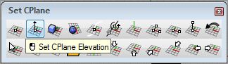
Utilize the Second icon labeled Set CPlane Pinnacle to just move the CPlane in its relative Z axis, and click to accept.
1.ii Rotating the CPlane
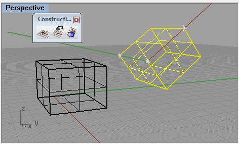
Employ Set CPlane: Rotate to rotate the Perspective CPlane ninety degress virtually the Y centrality.
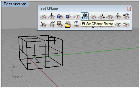 |  |
| Choose Gear up CPlane: Rotate with the Perspective view selected. | Hitting enter to set the rotation centrality at the origin. |
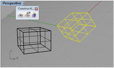
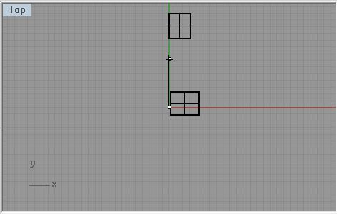 |  |
| With ortho on cull a point in Top view in a higher place the origin to set up the axis. | In Front view click to the right with ortho to set the start rotation. |
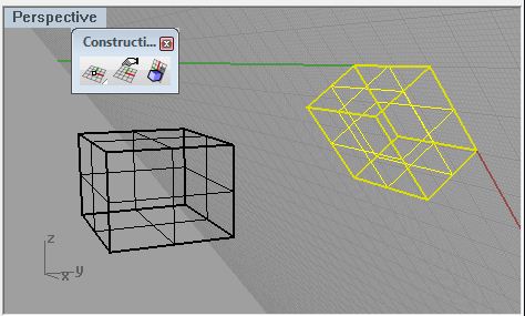
 |  |
| Then click above to rotate the CPlane 90 degrees. | Now in the Perspective view you can run across the grid is oriented in the ZY aeroplane. |
Return to the original CPlane by clicking on the Previous CPlane icon.
Next use the Set CPlane by 3 points icon to create an orientation relative to a diagonal on the box.
 | 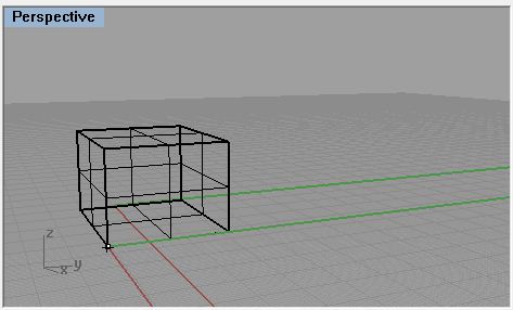 |
| With Perspective view selected click Set CPlane past three Points | With snaps on click on one corner of the box to set up the origin |
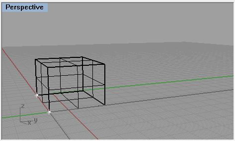 | 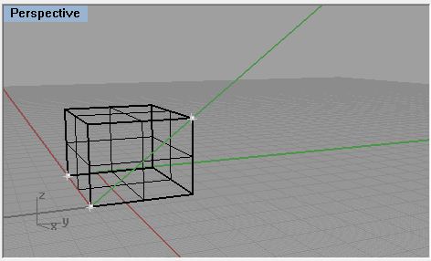 |
| Click on some other corner to prepare the X axis | Then click on a tertiary corner diagonal from the others to set the Y centrality |
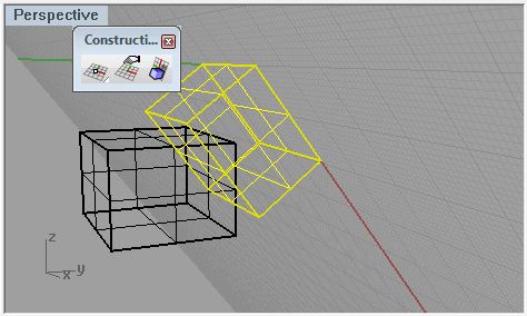
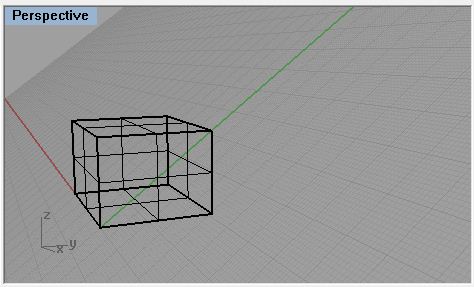 | 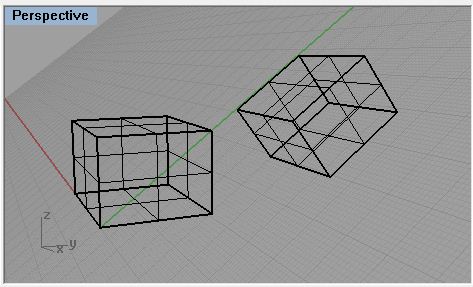 |
| This sets the CPlane through the box diagonally. | Drawing some other box in Perspective view. |
Other methods of manipulating CPlanes.
Set CPlane to Object
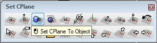
Sets the CPlane in-line with a part of an object, with the origin at the object'due south center.
Prepare CPlane to Surface
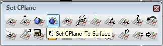
Sets the CPlane tangent to a point on an object's surface.
Fix CPlane Perpendicular to Curve
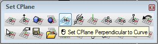
Sets the CPlane's 10 and Y axes perpendicular to a point on a curve.
Set CPlane to View
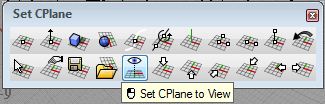
Creates a CPlane relative to the camera's viewing angle
two.1 Organizing created Coordinate Planes.
To save and load CPlanes.
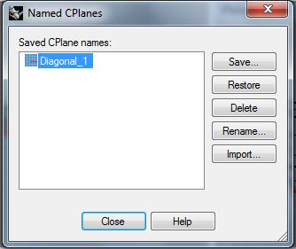
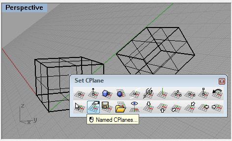 | 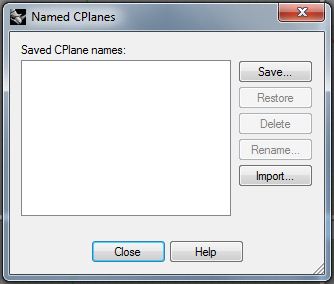 |
| Select the view and click Named CPlanes... | this brings upwards the Named CPlanes dialog box |
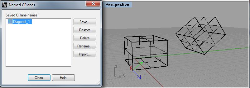
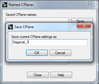 |  |
| Click Save and type in a name for the CPlane then striking OK | now the CPlane "Diagonal_1" tin can be referred dorsum to later on. |
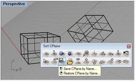 | |
| Alternately you can click the Save CPlane past Proper noun icon, type a name and printing enter to save the selected view's CPlane. |
The Named CPlanes dialog box can be used to restore saved CPlanes to the selected view by choosing the view and clicking Restore.
the highlighted CPlane is displayed in the view window as colored arrows.
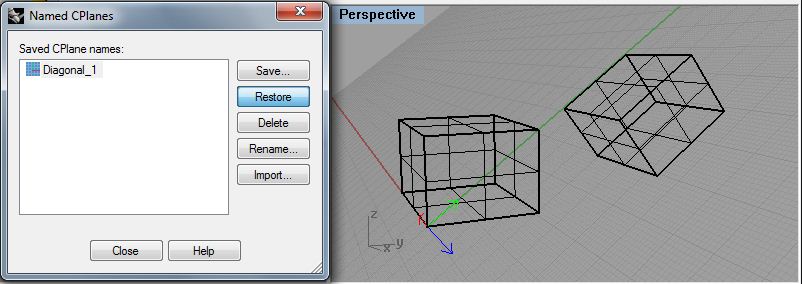
Clicking Restore applies the selected CPlane to the Viewport.
An alternate method to this is to right click the Salve CPlane by name icon and type the saved CPlane's name so press enter.
2.2 Preset CPlanes.
![]()
These six icons in the bottom right of the button bar volition apply a CPlane to the selected view that is relative to
the Global Coordinates :Summit, Bottom, Front, Dorsum, Correct, Left orientation respectively. This is an effective way
to pull upwardly normally used structure planes quickly and easily in the model space.
2.3 Mobile Construction Planes
A last method of manipulating the Construction Planes is to attach it to an object and have information technology always update relative to that object.
 | 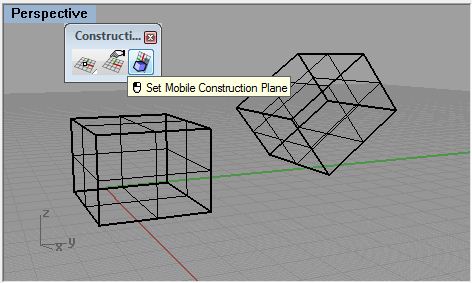 |
| In Perspetive View use the Previous CPlane icon to render to the default. | In the Construction Plane tool box click Set Mobile Construction Aeroplane |
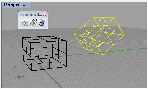 |  |
| Select the diagonal box and printing "A" enter to attach | select one corner on the box to fix the origin |
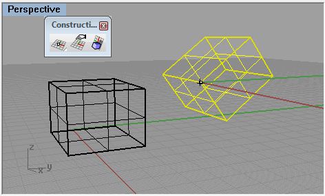
 |  |
| select the other two corners to set the Ten and Y axes | Press enter for automatic updates to the CPlane. |
 |  |
| Rotating the object rotates the attached CPlane as well | Translating the object will interpret the CPlane |
ayalathencestraes.blogspot.com
Source: https://web.arch.virginia.edu/sarc6710/Handouts/whshops2012/rhino/workshop4.html
Posting Komentar untuk "How to Draw on the Same Plane in Rhino"